PIXELHUE
HDR Format Conversion
HDR Format Conversion
1.Basic Knowledge
1.1 Dynamic Range
Explanation of Dynamic Range
The dynamic range describes the distribution of light intensity range from the darkest areas to the brightest areas in an image.
As shown in P1 below, from left to right are the image with low dynamic range, the original image, and the image with high dynamic range
respectively. It can be seen that:
1. The wider the dynamic range is, the clearer the details in the highlight and shadow areas will be
shown, and the pixel distribution in the histogram will be more balanced.
2. The narrower the dynamic range is, the more likely it is that the highlights will be overexposed and
the dark areas will be completely black. Almost all the details in the highlight and shadow areas are
lost, and the pixels are piled up at both ends in the histogram.
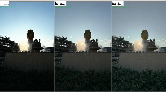
P1: Comparison Charts of Different Dynamic Ranges
1.1.1. Standard Dynamic Range (SDR)
SDR, or Standard Dynamic Range, is a technical standard used in early television and photography. Its characteristics include a relatively
low dynamic range in terms of image brightness and color. Typically, SDR uses 8-bit color depth, meaning each of the red, green, and
blue color channels has only 256 levels of gradation. Due to its limited dynamic range, SDR cannot simultaneously display details in both
bright and dark areas of a scene. It allows a maximum brightness of 100 nits and a minimum brightness of 0.1 nits, with details above 100
nits and below 0.1 nits being lost in SDR images.
1.1.2. High Dynamic Range (HDR)
HDR, or High Dynamic Range, is a processing technology that enhances image brightness and contrast. This technology enriches the
details in dark areas, making darker regions even darker while preserving more intricate color details. HDR can achieve a maximum
brightness of several thousand nits and a minimum brightness as low as 0.0005 nits. This significantly expands the details in areas of the
image with brightness levels above 100 nits and below 0.1 nits. As a result, the entire image appears clearer, more vibrant, and richer in
details.
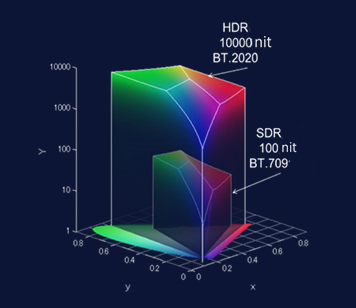
P2: Comparison between HDR and SDR Color Gamut Spaces
HDR10
Technically, HDR10 is limited to a peak luminance of up to 10,000 nits. However, the peak luminance of ordinary HDR10 content is 1,000
nits. HDR10 is not backward-compatible with SDR displays (that is, SDR displays are unable to display HDR10 content). On different
displays, such as HDR10 displays with relatively low color volume or peak luminance, static metadata can help adjust the displayed
content. However, the metadata of HDR10 is static, meaning it is the same for the entire video and there is no special adjustment for each
frame or different shot/scene.
HLG
HLG is also a standard for High Dynamic Range (HDR). HLG does not require metadata and is backward-compatible with SDR.
Compared with HDR10, its images can appear more vivid and attractive even on existing SDR display devices.
HDR10+
HDR10+ is an upgraded version of HDR10. It incorporates dynamic metadata, enabling fine adjustments of brightness, contrast, and color
for each frame of the image according to the scene. HDR10+ has improvements in dynamic range and color control compared to HDR10,
but its compatibility is relatively low.
Dolby Vision
Dolby Vision's 12-bit color depth can provide 68.7 billion colors, while HDR10 with a 10-bit color depth only supports a maximum of 1.07
billion colors. The larger the color depth range is, the more delicate and realistic the colors displayed in the video will be. Dolby Vision also
uses dynamic metadata and supports fine adjustments for each frame of the image. However, to use Dolby Vision, it must pass Dolby's
certification and a copyright fee needs to be paid.
HDR Vivid
HDR Vivid is an HDR standard developed under the leadership of Huawei. It supports 10-bit/12-bit color depths, which is the same as
Dolby Vision and HDR10+. Secondly, in terms of luminance, it can reach up to 10,000 nits, on a par with Dolby Vision. In terms of image
quality, HDR Vivid is actually no inferior to Dolby Vision. Compared with Dolby Vision, HDR Vivid has the advantages of being free and
having higher device compatibility.
Comparison of Parameters of Various Dynamic Ranges
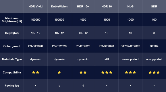
Chapter 1: Comparison of Parameters of Various Dynamic Ranges
Dynamic Ranges Supported by the PIXELHUE Switcher
Currently, PIXELHUE Switcher supports SDR input sources and output settings, as well as the input sources and output settings for two
types of HDR, namely HDR 10 and HLG.
1.2. Color Gamut
The Explanation of Color Gamut
The color gamut refers to the range of color representation. It is usually described by a bounded volume in a uniform color space and
represents the range within a chromaticity diagram or color space of a set of colors that meet certain conditions.
The Relationship between Dynamic Range and Color Gamut
Generally speaking, the color gamut defines the entire quantifiable range of colors. Different color gamuts have different quantifiable color
ranges. With the development of the industry, the quantifiable color range has been constantly expanding.
A high dynamic range requires a larger quantifiable color range to support its display. Therefore, a high dynamic range can achieve better
display effects only within a broader color gamut.
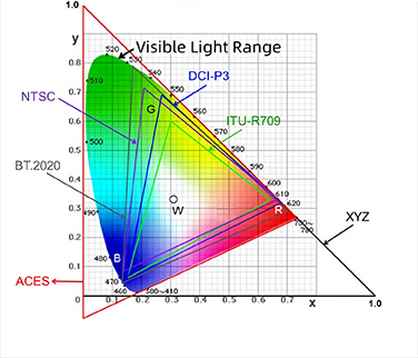
CIE 1931 Standard
The International Commission on Illumination (CIE) developed a set of standards regarding color perception in 1931. Through research
and experiments on the human eye's perception of light rays with different wavelengths, this standard established a system for describing
and representing colors. It quantified the visible light to the human eye and established the CIE 1931 Standard Colorimetric System.
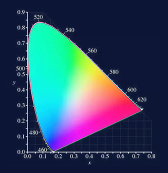
P3: CIE 1931 x-y Chromaticity Diagram
The Common Used Color Gamuts
In the television industry, commonly used color gamuts include NTSC, EBU, SMPTE C, BT.709, BT601, and BT.2020; the commonly used
color gamut in the film industry is DCI-P3; the IT industry uses Adobe RGB and sRGB color gamuts. In addition to these physical color
gamuts related to devices, some device-independent color gamuts that are larger than the visible light range of the human eye are also
used in transmission and production processes, such as XYZ and ACES.
Color Gamuts Supported by Pixelhue Switcher
As an industry-leading video processor, Pixelhue switcher is compatible with the mainstream color gamuts in the current television
industry and the commonly used color gamut in the film industry. It supports a total of four color gamuts: BT.601, BT.709, BT.2020, and
DCI-P3, providing customers with flexible choices for application.
1.2.1 BT601
In 1966, the EBU released the PAL standard and defined the EBU color gamut. In 1968, RCA and Conrac released the SMPTE C color
gamut. The EBU and SMPTE C color gamuts were respectively used as the standard color gamuts for 625-line and 525-line fluorescent
televisions. Both color gamuts were formulated according to the performance of high luminous efficiency phosphors, so their ranges are
similar. Later, they were both adopted by the ITU-R BT.601 standard and became the ITU-R BT.601 standard definition digital television
technical standard, known as the BT.601 color gamut. The BT.601 color gamut can reproduce 33.5% of the visible light color gamut.
1.2.2 BT709
In 1990, the ITU released the ITU - R BT.709 high - definition television standard. The BT.709 color gamut was also formulated based on
the performance of high - luminous - efficiency phosphors. Its color gamut is almost the same as that of the EBU in BT.601 and can
reproduce 33.5% of the visible - light color gamut. The R/B of the BT.709 color gamut is the same as that of the EBU, the y - value of G is
the same as that of the EBU, and the x - value is 0.30, which is the intermediate value between 0.29 of the EBU and 0.31 of the SMPTE
C. Therefore, the BT.709 and the EBU of BT.601 can be regarded as the same color gamut.
1.2.3 DCI-P3
In 2005, DCI officially released the V1.0 document and defined the DCI - P3 digital projector color gamut with reference to the color gamut
of film projection copies, which can reproduce 45.5% of the visible - light color gamut.
1.2.4 BT2020
In 2012, the ITU released the ITU - R BT.2020 standard. The BT.2020 color gamut no longer takes the performance of cathode ray tube
phosphors as the basis for formulating color gamut standards. Instead, it refers to the performance of new display devices (such as LCD,
OLED, laser, etc.) and can reproduce 63.3% of the visible light color gamut. It is currently the largest color gamut of display devices.
P4: The Comparison of Color Gamuts
1.3. Gamma
Restricted Definition of Gamma
In terms of visual perception, gamma represents the tonal reproduction of an image on electronic devices, where different gamma
characteristics yield varying tonal styles.
Narrowly defined, gamma refers to gamma correction in the television industry, which involves non-linear processing of video signal levels
at the source to correct the non-linear characteristics of cathode-ray tubes (CRTs).
The original purpose of gamma correction was to compensate for the non-linear response of CRTs. However, in modern display systems,
the role of gamma correction has shifted. Its main purpose is no longer to correct the non-linearities of display devices but to efficiently
allocate quantization resources, compress the dynamic range for transmission and recording, and optimize visual quality.
Gamma correction takes advantage of the human eye's non-linear logarithmic response. More quantization levels are allocated to dark
areas, where the human eye is more sensitive, and fewer levels are used for bright areas, where the eye is less sensitive. This non-linear
approach aligns with human visual characteristics, making it more effective than linear transmission or recording. It allows a larger
dynamic range to be represented with limited quantization resources. Without non-linear gamma correction, the 8-bit quantization used in
standard and high-definition TV broadcasting would be insufficient, requiring at least 9 to 10 bits.
Generalized Definition of Gamma
In a broad sense, gamma represents the brightness (or grayscale) characteristics of systems in the film and television industry, that is, the
light-to-electric conversion characteristics of the shooting system, the electric-to-electric conversion characteristics of the production
system, and the electric-to-light conversion characteristics of the display system, namely OETF, EETF, and EOTF.
OETF (Opto-Electronic Transfer Function): It is a transfer function that takes scene light as input and converts it into picture or video
signals as output, usually completed within the camera.
EETF (End to End Transfer Function): It is a transfer function that takes picture or video signals as input and outputs picture or video
signals. This process is completed in the video processor.
EOTF (Electro-Optical Transfer Function): It is a transfer function that takes image or video signals as input and converts them into the
linear light output of the display device, completed within the display device.
The Relationship between Dynamic Range and Gamma
For display systems, the gamma curve defines the nonlinear mapping relationship of the electric-to-light conversion and
determines the nonlinear change of the brightness information of the display system.
High dynamic range requires the ability to display more brightness information. Therefore, high dynamic range requires a
mapping relationship that can retain more light brightness information.
1.3.1 PQ (Perceptual Quantizer)
PQ is a transfer function developed by Dolby for HDR. It is a perception-based quantization method that utilizes the human eye's
perceptual characteristics of luminance and color to allocate image information to different quantization levels in order to achieve better
visual quality. PQ is referred to as an "absolute" standard, which means that for each input data level, there is an absolute output
luminance value that must be adhered to, leaving no room for variation.
1.3.2 HLG (Hybrid Log-Gamma)
HLG is a transfer function developed by NHK and BBC for HDR. It can provide some backward compatibility on SDR displays. HLG is a
hybrid transfer function, in which the lower half of the OEFT signal values uses a gamma curve and the upper half of the signal values
uses a logarithmic curve. The HLG standard is not an absolute standard; instead, it is relative. Regardless of the actual peak luminance
value of any given display, the EOTF gamma curve is always full-range.
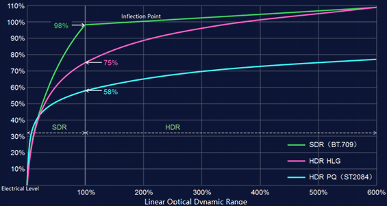
P5: Comparison of OETF Characteristics for SDR, PQ, and HLG
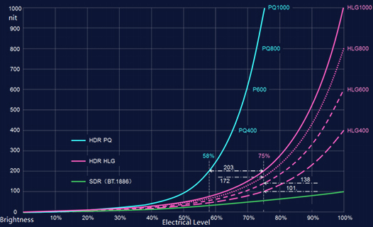
P6: Comparison of EOTF Characteristics for SDR, PQ, and HLG at Different Display Peak Brightness Levels
From the EOTF (Electro-Optical Transfer Function) characteristics of PQ and HLG under different display peak brightness levels, it can be
observed that PQ, adopting an absolute brightness system, has a unique EOTF curve. When the peak brightness of the display device
changes, the PQ curve only shifts the upper cut-off point. In contrast, HLG, which uses a relative brightness system, exhibits different
EOTF curves for different peak brightness levels. Therefore, HLG defines an OETF (Opto-Electrical Transfer Function) instead of an
EOTF, as the EOTF curve for HLG is not unique.
1.4 HDR Advantages (Why do We Need HDR Format?)
Brightness: HDR technology requires increasing the maximum brightness and reducing the minimum brightness of display devices,
thereby increasing the contrast between light and dark and showing more details.
Color gamut: HDR displays tend to use a larger "color gamut coverage" standard. Some HDR standard definitions will require the use of a
larger color gamut space, such as using the BT.2020 color gamut to achieve a larger color space coverage area. Compared with the
traditional BT.709 and NTSC definitions, its display color gamut space is more abundant.
Color depth: HDR can increase the color depth of display devices, thereby showing more color gradations and avoiding the appearance of
color bands or color blocks. Traditional displays are usually 6-bit or 8-bit displays, while HDR requires a bit depth of 10 bits or even 12 bits.
Dynamic mapping: HDR can dynamically adjust brightness and color according to different content and scenes to achieve better picture
effects.
2. HDR Conversion Scheme
2.1 Why is HDR Conversion Necessary
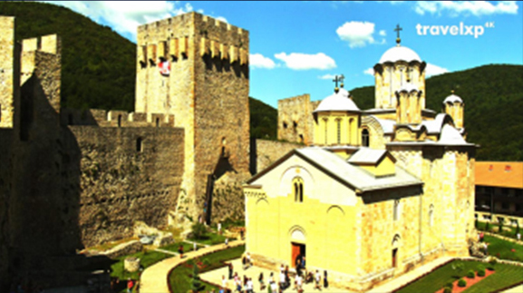
Color Distortion Due to Mismatched Input and Output Formats
When the color gamut or dynamic range of the input source differs from that of the output settings, color distortion can occur without HDR
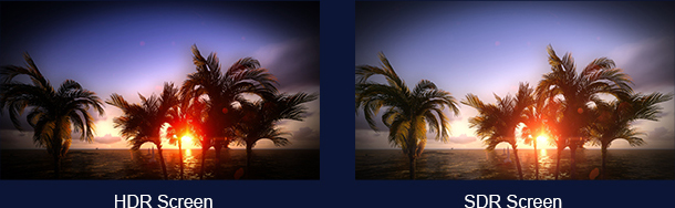
format conversion. For example, if an HDR10 input is sent to a device with output set to SDR and connected to an SDR display, the image
will appear overly bright, leading to color distortion. Conversely, if an SDR input is sent to a device with output set to HDR10 and
connected to an HDR display, the image will appear noticeably darker, also resulting in color distortion.
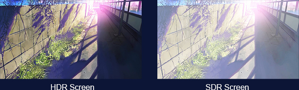
P7: HDR10 Content Displayed on HDR Screen and SDR Screen
P8: SDR Content Displayed on HDR Screen and SDR Screen
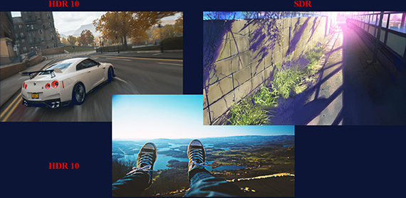
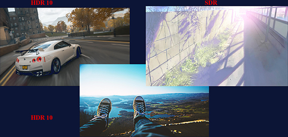
Layering Issues Due to Mismatched Input Source Formats
When multiple input sources are layered together, failing to use HDR format conversion to unify all sources to the same dynamic range
can lead to display issues. Regardless of the screen type, some layers in the output may appear overly bright or too dark, resulting in an
abnormal final image.
Proper Output After HDR Format Conversion
Output on HDR Display Without HDR Format Conversion
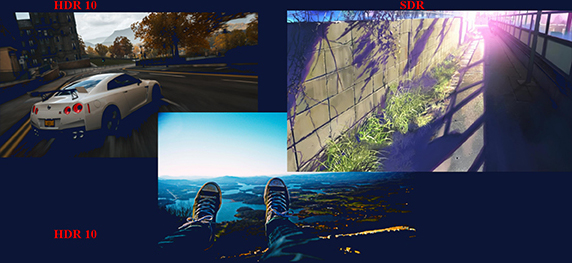
Output on SDR Display Without HDR Format Conversion
P9: Output Image After Multi-Layer Overlay
2.2 HDR Format Conversion Scheme
Each HDMI input interface of PIXELHUE device supports three dynamic range video source inputs: SDR, HDR10, and HLG. Regardless
of the color gamut of the input video source, it will be converted to the internal processing intermediate color gamut for processing inside
the device system. When the user sets the color gamut of the output HDMI interface, the internal system will convert the internal
processing intermediate color gamut to the color gamut set by the user.
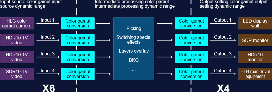
P10: HDR Scheme
3. The HDR Management Configuration of the Device
3.1 Enable HDR Format Conversion
If the device needs to input or output video images with HDR10 or HLG dynamic range, we can directly choose the format in the input
interface or the output interface.The HDR format conversion function of the device will be enabled.
The software path where this function switch is located is: Device ->Input Interface and Device -> Output Interface.
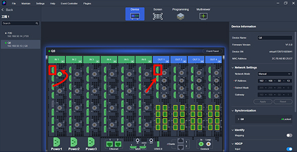
P11: Software Path for HDR Format Conversion
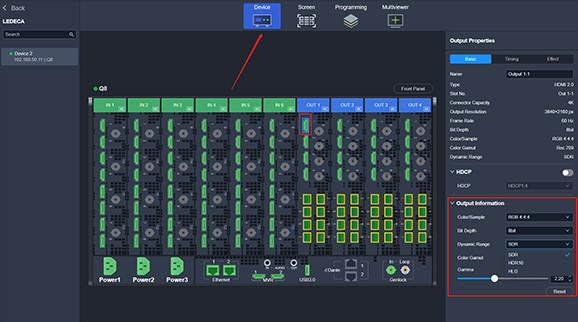
3.2 Input Configuration
This device supports viewing information about the input video source, such as color gamut and dynamic range.
The software path for viewing input video source information is: Device -> Input Interface.
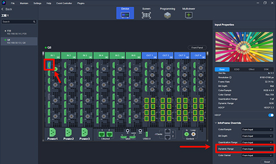
P12: Software Path Diagram for HDR Input Configuration
3.2.1 Metadata
The metadata of HDR is a kind of information attached to HDR video. It can help display devices display picture content in a better way.
The content of the metadata includes the maximum brightness, minimum brightness, average brightness, color gamut, etc. of the video.
When the input dynamic range is HDR10, relevant information will be displayed.
The HDR10 supported by this device uses static metadata. Therefore, the same metadata will be used throughout the entire video to
control the color and details of each frame. There will be no change between frames.
MaxFALL & Maximum Frame Average Light Level
The maximum value of the frame - average brightness, refers to the maximum value among the average brightness values of all frames in
the entire video. Usually, it is obtained by measuring the final delivered content after production is completed.
MaxCLL & Maximum Content Light Level
It refers to the brightness value of the brightest pixel point among all the frames of the entire video. Therefore, the value of MaxCLL will
generally be much greater than that of MaxFALL.
Mastering Display Max Luminance
When producing the HDR10 input source video, debugging needs to be carried out with the setting information of a certain device (HDR
television, a certain standard display). In the process of master video production, the maximum brightness of the display used is called
Mastering Display Max Luminance.
Mastering Display Min Luminance
In the process of master video production, the minimum brightness of the display used is called Mastering Display Min Luminance.
Definition of White Point
White point refers to the coordinates of white in the encoding color gamut of the input video.
The metadata contains the information of the primary color coordinates of the mastering display (Mastering Display Color Primaries),
which reflects the coordinates of red (R), green (G), blue (B), and white (WP) of the mastering display on the encoding color gamut. The
area enclosed by the three points of RGB is the color range supported by the video. Therefore, the definition of white point actually reflects
the color gamut information of the video.
3.2.2 Input Source Information Overwrite
In this device, the color space/sampling rate, bit depth, quantization range, dynamic range, and color gamut information of the input video
source can all be overwritten manually by the user. The function of this feature is that when there is no accurate information with the
interface chip's parsing or there is an abnormality in the input video source itself, the user can still manually modify the parameters of the
input video source to ensure that the video picture is normal.
Follow Input Source
When the input source information overwrite is set to follow input source, the information of the input video is completely obtained by the
interface chip's parsing. Under normal circumstances, using the default "follow input source" can obtain a normal input video. When
abnormalities such as color cast, overexposure, or underexposure occur in the input video when using the "follow input source" option, the
user can manually adjust relevant parameters and overwrite the input source information.
Tone Mapping
SDR uses a peak brightness of 100 nits and the BT.709 color gamut to create and display content. However, HDR is different and can
display content with a peak brightness of 1,000 nits, 4,000 nits, or other values. Consumers may watch this content on a display with only
a peak brightness of 100 to more than 1,000 nits. In order to enable high-brightness video content to be displayed normally on a display
whose peak brightness does not meet the video's peak brightness, a mapping needs to be done from the video brightness domain to the
brightness domain supported by the display. The function of remapping the total brightness range in the content according to needs to the
brightness of the display is called tone mapping.
Peak Brightness
Peak brightness refers to the brightness of the brightest area of the input video image. Overwriting the peak brightness of the input image
is to replace the "maximum content brightness" in the metadata with a custom value set by the user. After modifying the peak brightness,
the brightness domain of the conversion from the input source video image to the intermediate processed video image will change.

(a) maximum content brightness 1000, content display at peak brightness 1000
(b) content display at peak brightness 300

(c) content display at peak brightness 5000
P13: Effect of Adjusting Input Source Peak Brightness on Output Image
Ambient Light Brightness
Ambient light brightness refers to the illumination intensity of the environment around the shooting equipment during the shooting process
of the input video image. Users can adjust the ambient light brightness to obtain the best output display effect.
3.3 Configure Output
There are two setting methods for the color gamut, dynamic range, and other information of the output video image of this device under
different circumstances.
3.3.1. When the interface is not involved in screen construction:
The software path for image output settings is: Device -> Output Interface.
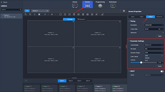
3.3.2. When configure screen with output connectors:
The software path for image output settings is: Screen Setup -> Output.
3.4 Notes
3.4.1.The HDR feature requires manual configuration. If a specific format is explicitly selected, the video source data will be processed
according to the logic of the specified format, regardless of whether the video source data matches the selected format.
3.4.2.After enabling HDR, if the connected video source is not in the corresponding HDR format, the display effect on the screen will be
incorrect due to processing based on the selected HDR parameters. Users need to correctly set the HDR parameters according to the
input source to enable proper HDR support.
3.4.3.When HDR is disabled, the system processes the video as SDR. If an HDR source is connected in this mode, the display effect on
the screen will also be incorrect.
3.4.4.HLG sources can be recognized as SDR, but the display effect will be compromised.